

Components of the electrode system
Based on the experience from the MLL-IonCatcher system [1,neumayr06], a longitudinal injection has been implemented for the cryogenic gas cell, where the ions will enter through an entrance window of 60 mm diameter (e.g. Titanium, thickness 2.5-3.5 micron, thin Kapton foils are planned to be tested for their performance under cryogenic conditions). In contrast to the existing gas cell devices at SHIPTRAP and Garching, the entrance window and its support grid will act as first DC electrode. Thus the full length of the gas volume will be available for ion stopping and extraction. Therefore the window support flange has been isolated against the end flange of the vacuum vessel as well as against the DC electrode system. Here the same metal-ceramic bonding technique is used used as already successfully operated for the insulation of the nozzle electrode. This technique defines the height of the window flange, that can be seen on Fig. 1. The entrance foil is supported by an etched planar support grid and sealed with a 1 mm gold wire, while the support flange can be sealed against the cage end flange by a conventional CF100 copper sealing.
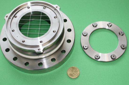
Fig. 1: Flange unit for the the isolated metallic entrance window to the cryogenic gas cell acting as first electrode. The electric isolation is achieved via a metal-ceramic bonding technique.
Subsequently the stopped ions will be guided by an electrical field gradient of >= 10 V/cm towards the extraction nozzle. The electrical field will be provided by 8 DC electrode segments, each consisting of a thin (0.2 mm) steel foil with a width of 28.4 mm and an inner diameter of 260 mm. Fig. 2 shows a photograph of the DC electrode system. The DC electrode system has been mounted to support rods (diameter 6 mm), isolated by ceramic tubes and fixed in distance by ceramic spacer tubes. The external boundary of the DC electrode system will be given by thin (0.3 mm) stainless steel foils covering the radial circumference of each DC electrode segment. These foils replace the mesh structure so far used at SHIPTRAP. Due to the cryogenic operation the increased surface area will not deteriorate the vacuum properties. The DC gradient will be provided by a voltage divider directly mounted to the electrode system, thus drastically reducing the number of required electrical feedthroughs.
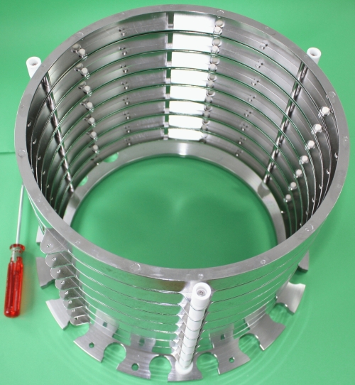
Fig. 2: Eightfold segmented DC electrode system. The individual segments are supported by 3 steel rods (diameter 6 mm), which themselves are electrically isolated via ceramic tubes from the eye ring holders. The distance between the segments is preserved via ceramic spacers.
The ions will be further guided towards the extraction nozzle by an RF funnel system, consisting of 75 individual ring electrodes with inner diameters ranging from 266 mm down to 5 mm near the extraction nozzle. In the backward region of the funnel 55 electrodes will be mounted each with a thickness of 1 mm and distances between neighbouring electrodes of 1 mm, while for the 20 electrodes near the nozzle exit higher electrical fields can be reached by a reduced thickness and spacing of the electrodes of 0.5 mm. The ring electrodes have been laser-cut and great care has been taken by electropolishing and manual post-treatment of the ring edges to ensure smooth radii. Each of the ring electrodes is mounted to three support rods and has been isolated with respect to their neighbours by ceramic spacers at the support rods, thus reducing the capacitance of the funnel systems. The innermost, thinnest 20 ring electrodes are additionally kept at constant distance by ceramic spacers. Thus 6 support rods are mounted to a base plate and covered at their ends by ceramic caps in order to prevent sparking to the adjacent DC electrode. In order to prevent charging of the end caps they are in turn covered by steel caps on ground potential. Fig. 3 shows the RF funnel assembly that guides the ions towards the extraction nozzle.
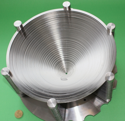
Fig. 3: Design of the RF (+DC) funnel system with 75 ring electrodes.
The last electrode of the buffer gas stopping cell is the extraction nozzle, which is electrically isolated using the same metal-ceramic soldering technique as already applied to isolate the entrance window. The nozzle throat diameter is 0.6 mm, as presently used for the SHIPTRAP gas cell. Fig. 4 shows a photograph of the nozzle flange with the nozzle electrode in the center.
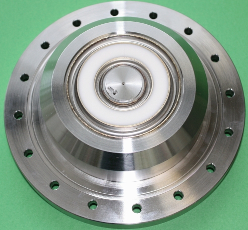
Fig. 4: Nozzle flange carrying in its center the isolated nozzle with a diameter of 0.6 mm.
While the window and nozzle flanges, drawing from the metal-ceramic soldering that can sustain also cryogenic condition, have been manufactured by an external provider (FRIATEC), the DC electrode and funnel system have been manufactured by the Graching mechanical workshop. After adding the electrical contacts to the various electrodes, cryogenic performance tests will be performed first separately on each of the electrode system components before integration into the vacuum and cryogenic tank of the new gas cell, which is planned for summer 2010. With the upgraded cryogenic buffer gas stopping cell and increase of the overall stopping and extraction efficiency from presently about 4% up to 20% is envisaged, thus allowing to extend the measurement capabilities of SHIPTRAP significantly to transuranium species beyond the presently accessible region up to Z=103.
References:
1. M. Block et al., Nature 463 (2010) 785.
2. J. Neumayr et al., Nucl. Instr. Meth. B244 (2006) 489.
3. J. Neumayr et al., Rev. Sci. Instr. 77 (2006) 065109.